
Rapid Prototyping China vs Alternatives: Which Material–Process Pair Wins Your Part
A prototype exists to answer a question, and the process that makes it should match the question being asked. Fit and form can be answered with a printed plastic shell. Function, tolerance, and material behavior demand real metal cut from real stock. And the pair you prototype with is the pair you will most likely scale, so the material–process decision made at the prototype stage tends to follow the part into production. This guide is for the engineer or sourcing lead who needs test parts fast and does not want to re-source when volume arrives. It sets out where machining-based rapid prototyping in China wins against 3D printing, casting, MIM, injection molding, and sheet-metal fabrication, where each alternative deserves the job, and how to keep the winning pair intact when the prototype ramps.
What is a material–process pair, and which pair should a prototype be built on?
A material–process pair couples the grade with the way it is shaped: 6061-T6 machined from plate, the same alloy die-cast, or 316L stainless printed in powder. The pair — not the process alone — sets the tolerance the part can hold, the strength it can prove, and the documents that ship with it. Machined prototypes answer the strongest question: they use the production alloy in wrought form, at production tolerance, on a process that already exists. That is why a machining manufacturer that holds ±0.003 mm on milled and turned features and reaches ±0.002 mm with precision grinding is the natural baseline for a functional test part.
Prototyping compounds the decision because the answer is wanted in days, not months. Machining wins that race on a floor with parallel capacity: 50+ 3-axis centers, 20+ 4-axis, 20+ 5-axis, 25+ lathes, and 7+ grinders across a 6,800 m² facility staffed by 100+ people, with milling, turning, mill-turn, and grinding under one roof. Simple parts ship in about 3 days, standard parts in about 7, and complex parts — or those with surface finishing — in about 30. When a buyer can order a single part at an MOQ of 1 piece and watch the quoted lead time against the real one, the prototype validates the schedule as well as the part.
The error to avoid is choosing a process because it sounds fast, then discovering the prototype cannot prove what the design actually needs. Print the shell that only needs to look right, but machine the part that must carry load, hold a fit, or seal. The pair should answer the loudest question on the drawing.
When does machining beat 3D printing for the first test parts?
3D printing wins a narrow slice of prototyping, and it wins on geometry and iteration rather than on material truth. Use it for one to ten units of a shape that would fight a mill — internal channels, lattices, organic curves — or for a fit-and-form check while the design is still moving. Printing absorbs geometry changes without fixtures or programs, needs no tooling, and returns a part in days, which is why it anchors early concept work.
Printing loses precisely where a functional prototype must deliver. A printed metal part is layer-bound rather than isotropic solid stock, so load, fatigue, and thread-holding pay for the difference. Its tolerance band sits far above machining — metal printing typically lands in the ±0.1–0.2 mm range with a layer structure on every surface — so a feature that must locate, seal, or press-fit cannot stay printed. And the per-unit economics do not improve with volume the way machining's do. The mature pattern is a handoff: print the concept while the design settles, then machine the functional prototype and the production part from real stock when tolerance, material, and strength are locked.
When does casting or MIM take the part, and what still has to be machined?
Casting wins the economic crossover, not the quality argument. A die is expensive and takes weeks, so a cast body only pays once volume is high enough to amortize the tool — typically thousands of parts for a small, stable component. Below the crossover, machining from bar or plate wins for one-offs, bridge runs, and prototypes, because there is no tool to pay for. Above it, the die earns the envelope and the low per-part cost, and machining earns the features that decide fit and function.
Metal injection molding (MIM) occupies a different corner: small, complex metal parts at volume high enough to justify a mold, where the geometry is too intricate to machine economically. MIM suits stainless and low-alloy parts in small-to-medium sizes. The trade is the same as casting — the part shrinks during sintering, the body carries the tolerance of the process rather than of wrought stock, and any critical dimension must be machined or specified against that shrink.
What never changes is the finish line. A cast or MIM body carries porosity risk, draft, or shrinkage that a machined feature does not, so the production part takes the hybrid shape: the die or mold produces the body cheaply, and the machining floor cuts the bearing seats, sealing faces, bolt patterns, and datum surfaces afterward at ±0.003 mm, verified on a CMM. Porosity and shrink belong to the body; the tolerance belongs to the machining. Buyers who skip that step — who assume a part that leaves for casting never has to come back — are the ones who discover the second supplier at the worst moment.
When does injection molding win a part that looked machined, and what do you give up?
Injection molding wins a plastic enclosure at stable, high volume. Once the mold exists, molding produces thousands of identical parts fast, and no subtractive process competes on that ground. For a thin-walled housing with molded-in bosses, clips, and finish, molding is the pair that wins, but only after the design is frozen and the volume is real, because the mold is a steel commitment that takes weeks.
The tolerance question is where molding gives ground. Molded plastic holds a band set by resin shrinkage — typically ±0.1–0.5 mm depending on the resin and the part size — so the mold holds the tolerance of a plastic body, not of a precision feature. A bore that must locate a bearing, a seat that must seal, or a threaded insert that must carry load is machined after molding. On this floor that machining runs to ±0.003 mm with proof on a CMM report, which is how a plastic part ends up holding a real seat. Molding the body and machining the critical faces is not a workaround; it is the standard engineering answer.
Do not treat these processes as rivals to be picked once. They are tools with different cost curves, and the winning configuration for most products is sequential: machine the development units now while the mold is cut in parallel, then mold for steady-state volume and machine the critical features on the molded parts.
When does sheet-metal fabrication deserve the part, and where does it stop being the answer?
Sheet metal and stamping deserve a part that is thin, flat, or box-like and is heading for volume. A stamped bracket or enclosure replaces hours of machining with seconds of press time once the tool exists. The trade is dimensional: stamping holds a band roughly an order of magnitude looser than machining, features are limited by the tool and by bend radii, and the material is a sheet grade with a thickness tolerance of its own. A stamped part that needs a precision bore or a datum-machined edge still comes back to machining for those features, exactly as a cast or molded body does.
For prototyping, sheet-metal work is often the right first step for an enclosure that is clearly headed to stamping, because it validates the flat pattern and the bend geometry without waiting on hard tooling. But a prototype that must prove a machined feature — a tight bore, a sealing face, a threaded boss — cannot be validated in sheet. Match the prototype route to the production route, and machine the features that sheet metal cannot hold.
Which material–process pair wins your part? A decision table for the quote stage
Start from the requirement that dominates the part, not from the process you already know. This table is the working version of the whole argument.
| If your part is… | The material–process pair that wins | Why |
|---|---|---|
| A fit-and-form check while the design is still moving | 3D-printed concept, then machined functional parts | Printing absorbs geometry changes and ships fast; machining holds the tolerance the released design needs |
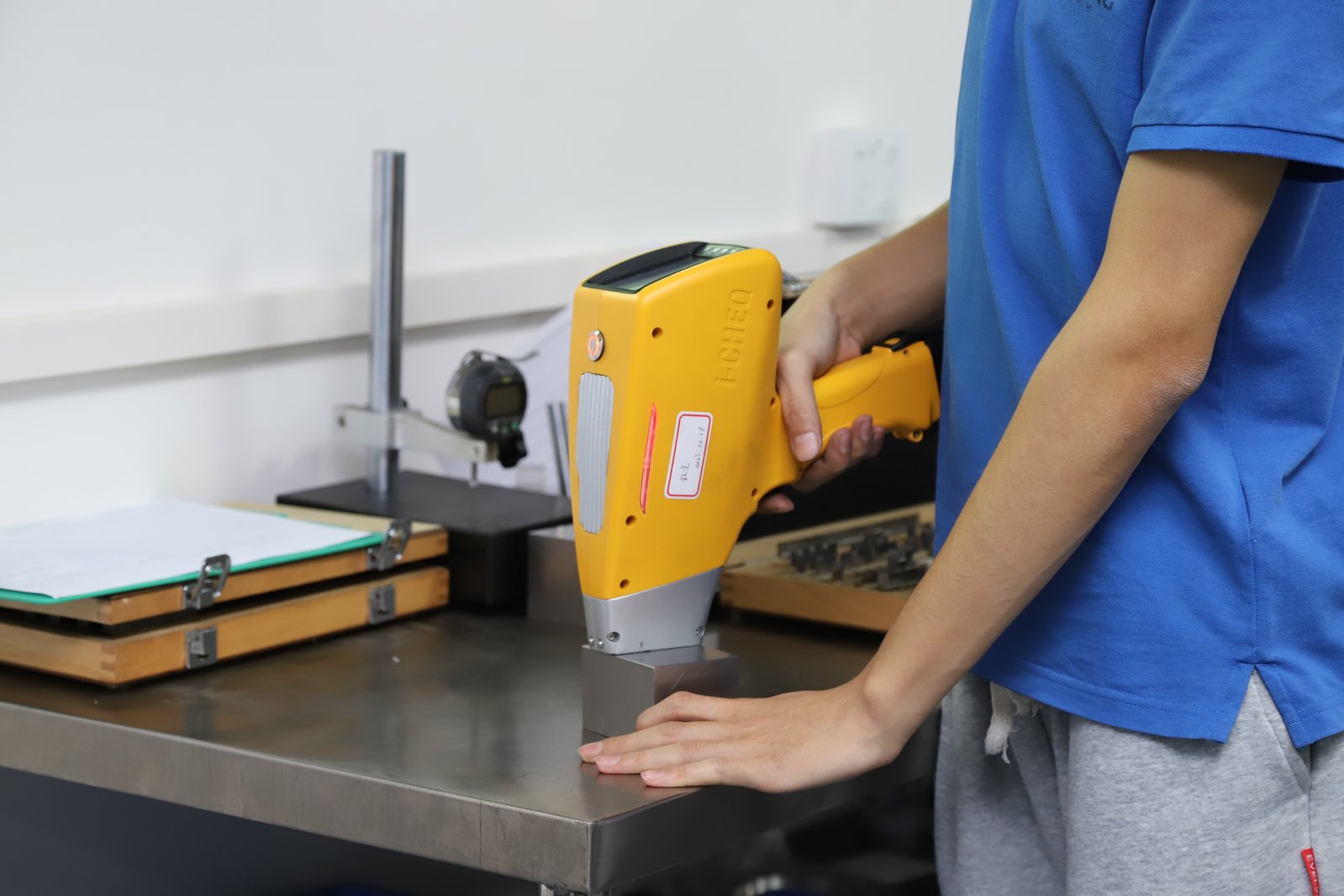
| A metal part that must carry load or hold ±0.003 mm features | Machined from plate, bar, or billet | Machining uses the real alloy in wrought form, holds the tight band, and ships with XRF-verified material |
| A thin-wall metal housing headed for high volume | Die-cast body with machined critical features | The die gives the envelope and low per-part cost; machining holds the seats, bosses, and bolt patterns |
| A small, intricate metal part at high volume | MIM body with machined critical dimensions | MIM reproduces complex small geometry cheaply at volume; critical features are machined after sintering |
| A plastic enclosure at stable high volume | Molded body with machined critical faces | Molding gives thin-wall geometry and finish; machining holds the real seats after resin shrinkage |
| A high-volume stamped or sheet part needing a precision feature | Stamped or formed body with machined datums | The press makes the body fast and cheap; machining recovers the tolerance stamping cannot hold |
| Any part whose drawing has not been reviewed | Machined prototype at MOQ 1, with a DFM review before tooling | The cheapest place to find a datum problem or an over-toleranced feature is before the die or mold exists |
Quantity does the heavy lifting. Below the crossover, machining wins on total cost, on speed, and on material truth; above it, the alternative wins the body and machining keeps the features that matter. The most common sourcing error is choosing a process before quantifying the crossover, and the second is assuming a part that leaves for casting, molding, or stamping never has to come back.
How do you keep the prototype's pair when the part ramps to production?
The prototype that validates the design should be the process that scales. On a one-floor manufacturer, the ramp is three phases: a prototype at one piece, a pilot at low volume, then production at volume, with the same machines, operators, and inspection bench running all three. That continuity is the quiet advantage of machining-based prototyping — the part does not change suppliers, does not get re-learned, and does not carry a new queue when volume arrives.
The discipline that keeps the pair intact is to prototype in the production material. Aluminum 6061 for a part that will run in 6061, stainless for a part that will run in stainless, titanium or magnesium when the design demands them — every lot XRF-checked against its mill certificate so the alloy you test is the alloy you scale. A prototype printed in a look-alike plastic validates the shape and nothing else. When the drawing carries tolerances, the fastest way to lose the ramp is to test a part that cannot hold them.
Surface finishing belongs in the same logic. If the production part will be anodized or passivated, the prototype should carry the same finish, because finishing changes dimensions and surface behavior. On this floor, finishing and heat treatment are coordinated under one roof, so the finish the prototype proves is the finish the production part receives. And the lead time for a finished part is quoted honestly: it sits in the ~30-day tier rather than in a number that forgets the anodizer.
How do you write the winning pair into an RFQ so every quote prices the same part?
Put the pair on paper before the RFQ goes out, and the responses you get back become comparable. Five fields are enough. Name the exact alloy and condition — "6061-T6," not "aluminum." Mark the tolerances on the features that control function, and leave the rest at a general standard. State the finish, because anodizing changes the schedule as well as the price. Give the quantity and the annual volume if you know it, so the shop can plan the ramp. And attach a STEP or IGES file plus a toleranced 2D drawing so the quote is priced against geometry, not against a description.
Then ask the questions that separate a schedule from a slogan. Which tier does the part fall into, and what would push it to the next one? Which machines run it, and how many of that type are open this week? Which tolerance does the print actually require, and where can a feature be loosened without losing function? A manufacturer that answers in specifics is showing you a plan; one that answers in adjectives is showing you a hope. The schedule behind the quote is the lead time the pair actually delivers, and with an MOQ of 1 piece you can test it on a single part before you commit volume. For the full process and capacity picture behind a fast prototype, the rapid prototyping services overview on this site is the place to start, and the parts guide shows how geometry, material, and tolerance set the schedule. The rapid prototyping hub ties the 3 / 7 / 30-day tiers, capacity, and delivery into one date you can plan around.
Frequently Asked Questions
Is 3D printing faster than machining for a functional prototype?
For a one-off concept shape, printing can ship in days with no tooling. For a functional part that must carry load, hold a fit, or prove the production material, machining is the route — simple parts ship in about 3 days, standard parts in about 7, from a floor with 100+ machines. Print the concept, machine the function.
What tolerances can a machined prototype hold?
Milling and turning hold ±0.003 mm on critical features, and precision grinding reaches ±0.002 mm for sealing and seating surfaces. Process capability is tracked at Ppk ≥ 1.67 at the initial study on key characteristics and Cpk ≥ 1.33 on general characteristics. Capability is reported per characteristic: every report names the feature, its tolerance band, the sample size, the sigma method, and the study window. Under SPC, and critical geometry is verified on CMMs and shipped as reports, not pass/fail stamps.
When is die casting cheaper than machining?
Above the crossover volume, where the die cost is amortized across enough units that the low per-part cost beats machining — typically thousands of parts for a small, stable component. Below that, or for prototypes, spares, and bridge runs, machining from plate or bar is the economical route, and cast parts that need precision still have their critical features machined.
Can I prototype by machining and produce by molding?
Yes, that is the standard bridge. Machine the development units to validate design and schedule while the mold is being made, then mold for steady-state volume and machine the critical features on the molded parts. The same factory can hold the early machining and the follow-on feature work.
Which materials can be machined for a prototype?
Aluminum, stainless steel, carbon and alloy steel, brass, copper, titanium, and magnesium, plus engineering plastics — with every lot XRF-checked against its mill certificate. Machining from real stock means the prototype tests the production alloy, not a stand-in.
What is the minimum order quantity for a prototype?
The MOQ is 1 piece. A single prototype validates the design, the tolerance, and the quoted lead time before volume is committed, and the same floor scales that prototype to pilot and production without re-sourcing.
Do you offer 3D printing, casting, or molding alongside machining?
Machining runs in-house — 3-axis, 4-axis, and 5-axis milling, turning, mill-turn, and grinding on a 6,800 m² floor. 3D printing, die casting, MIM, injection molding, and stamping are coordinated through vetted partners, with critical features machined and verified in-house on the same CMMs so the quality system does not break at the handoff.
Not sure which material–process pair should make your prototype?
Email the STEP or IGES model and the toleranced 2D drawing to [email protected] or call +86 13126536955. You will get a design-for-manufacturing review that names the process path — including which features must be machined regardless of the process that makes the body, and whether the part should be printed, machined, cast, molded, or run as a hybrid.